

You do the following:
■ Explore views of a model.
■ Explore model properties using the interface.
■ Explore model properties using the interface.
The completed exercise
Completing the Exercise
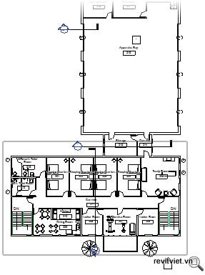
To complete the exercise, dowload i_rac_essentials_ui.rvt or m_rac_essentials_ui.rvt, follow the steps in the onscreen exercise.Explore Views of a Model
1. Open i_rac_essentials_ui.rvt or m_rac_essentials_ui.rvt. The file opens in the default 3D view of a completed project.Note: The illustrations in the exercise may vary depending on how you navigate in the project. In addition, the illustrations for the metric dataset will be slightly different from those shown here.
2. Examine the tab names on the ribbon.

3. Click each tab and examine the panels that they contain. Notice the organization of these tabs and where different tools and options are found.
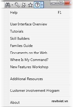
4. On the InfoCenter toolbar at the upper-right corner of the screen, expand the drop-down for Help, as shown below.
5. Press F1 to open the Revit Architecture User's Guide window. Ensure that the Contents tab is active.
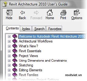
Become familiar with this help system. You can continually utilize this system throughout your learning process and beyond.
6. Close the Revit Architecture User’s Guide window.
7. Examine the Project Browser. It lists all the views associated with the building model. Notice that the default 3D view is bold, indicating it is the active view.
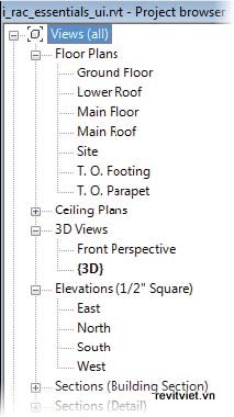
The Project Browser always contains all the views of a model and is used to navigate between the views. You can easily create and name new views as required in your design process.
8. To examine the different views available in this model, in the Project Browser:
■ Under Views (All), Floor Plans, double-click Ground Floor. This activates the view.
■ Activate other floor plan views.
■ Activate the elevation views.
9. In the Project Browser:■ Activate other floor plan views.
■ Activate the elevation views.
■ Expand the Sections (Building Sections) and Sections (Detail) branches.
■ Ensure that the Schedules/Quantities branch is expanded.
■ Activate the Door Schedule and Room Schedule views.
Note: You will not be working with the Families or Groups views in this exercise.
10. Return to the default 3D view.■ Ensure that the Schedules/Quantities branch is expanded.
■ Activate the Door Schedule and Room Schedule views.
Note: You will not be working with the Families or Groups views in this exercise.
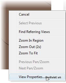
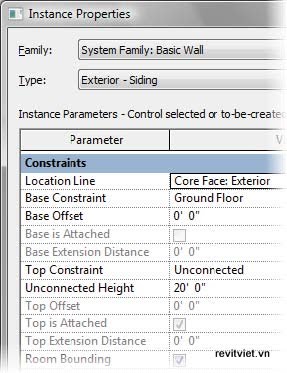
11. Right-click anywhere in the view window. Notice the context menu for this 3D view and click View Properties.
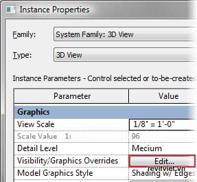
12. In the Instance Properties dialog box, for Visibility/Graphics Overrides, click Edit in the Value field.
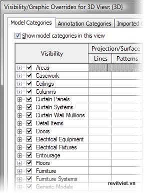
13. In the Visibility/Graphic Overrides dialog box, notice the visibility settings for this view.
14. Click Cancel in both the dialog boxes.
15. In the view window, place the cursor over the large pitched roof. The edges will highlight and a tooltip and the status bar display information about the roof.
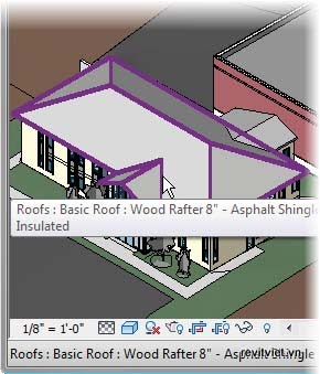
16. Click to select the pitched roof. The selected roof displays in blue. A contextual tab named Modify Roofs opens on the ribbon. Notice the tools available on this tab.
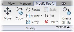
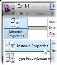
17. Right-click the selected roof. Click Elements Properties to open the Instance Properties dialog box.

Note: To open the Instance Properties dialog box, you can also click the Element Properties drop-down > Instance Properties on the Element panel of the Modify Roofs tab.
18. In the Instance Properties dialog box:
■ Notice the properties of the roof.
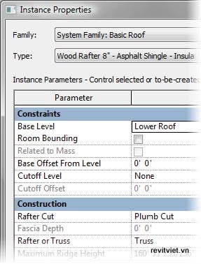
■ Click Cancel to close the dialog box.
19. Examine the View Control Bar at the bottom of the application window. Move the cursor over the tools on the View Control Bar and view the tooltips.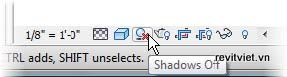
20. Click View tab > Windows panel > Close Hidden. This closes the different views you opened while exploring the model using the Project Browser.
Explore Model Properties Using the Interface
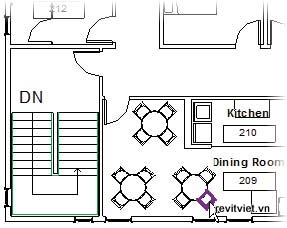
1. In the Project Browser, under Views (All), Floor Plans, double-click Main Floor to open the view.2. To zoom in to examine a portion of the view at close range:
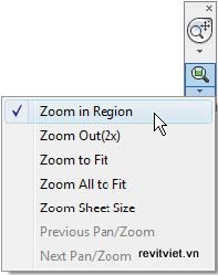
■ On the Navigation Bar at the right of the view window, click the drop-down arrow under the Zoom tool.
■ Ensure that Zoom in Region is selected.
■ Ensure that Zoom in Region is selected.
4. In the lower-left room, move the cursor over a chair to highlight it. The chair type is displayed in the tooltip and on the status bar.
5. In the lower-left room:
■ Move the cursor over the wall below the chair to highlight the wall.
■ Click to select the wall. The color of the wall changes to blue indicating the selection. The wall type is displayed in the Type Selector drop-down on the Modify Walls tab.
■ Click to select the wall. The color of the wall changes to blue indicating the selection. The wall type is displayed in the Type Selector drop-down on the Modify Walls tab.
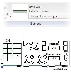
■ Notice the wall properties. If you change these properties, only the selected wall properties change.
■ Click Cancel to close the dialog box.
8. Examine the panels on the Modify Walls tab. Notice that the tab displays tools for modifying the selected wall.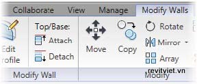
9. Click Home tab > Build panel > Wall. A contextual tab named Place Wall opens. Notice that the Options Bar below the ribbon displays options such as Location Line, Chain, and Offset for sketching or placing new walls.
10. Click Place Wall tab > Selection panel > Modify to exit the Wall tool.
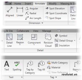
11. Click the Annotate tab. Notice the tools that are available on this tab.
12. In the view window, select the southern exterior wall as selected previously.
13. Open the South elevation view. Notice that the wall remains selected.
Note: Do not clear the wall selection. Reselect it in this view if you cleared it accidentally.
14. Open the default 3D view.
15. In the view window:
■ Zoom in to the view and notice that the wall is still selected.
■ Clear the selection by clicking away from the wall.
16.On the View Control Bar:■ Clear the selection by clicking away from the wall.
■ Click Model Graphics Style to open the
associated list.
■ Click Wireframe to change the view to
wireframe.
associated list.
■ Click Wireframe to change the view to
wireframe.
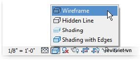
■ Apply the other model graphic styles.
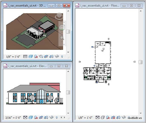
17. Return to the Shading with Edges style.18. Click View tab > Windows panel > Tile to display all the views that you have opened.
19. On the Navigation Bar in the active view:
■ Click the Zoom drop-down.
■ Click Zoom All to Fit. Notice that each view is zoomed to fit within its tiled window.
20. Close the file without saving changes.
■ Click Zoom All to Fit. Notice that each view is zoomed to fit within its tiled window.
No comments:
Post a Comment