

View elements are essential to the process of creating a Revit model. You can use views, such as the plan, section, elevation, and 3D views, to visualize a model as it is being built and generate the construction documentation. Each view has specific properties that can be used to modify its graphical display, independent of the other views. However, changes made to model elements, such as beams, columns, and walls, are reflected in all associated views.
The following illustration shows four different views tiled in the view window: a framing elevation, a 3D view, a wall elevation, and a framing plan.
Objectives
After completing this lesson, you will be able to:
- Describe views.
- Explain the use of view properties.
- State the recommended practices for working with views.
About Views
The Project Browser displays a list of all project views. These views display different representations of the same structural model. When you open a new view, the views that were already open remain open and their settings do not change.
Definition of Views
Views provide a way of visualizing and working on a building model. You use views to display a model from different directions and reference points that help you build the model. In addition, you use views to generate plans, elevations, sections, details, and schedules that are used to assemble construction documentation.
When you start a project, certain views are created by default based on the project template that you select. You can edit the properties of these views and create new views, as required. You can also duplicate existing plan and 3D views to create new views.
You can navigate within a view using the mouse wheel, Steering Wheels, or the view cube, and switch between views in the middle of an activity. For example, you can select a floor in 3D view and edit it in plan view. However, only one view can be active at any given time.
Bidirectional Associativity
Bidirectional associativity ensures that the changes made in one view automatically reflect in all the
associated views. Bidirectional associativity applies to every component, view, and annotation in a
project.
For example, a change made to the spacing of the floor framing in a plan view is reflected in all the
associated views, such as section views.
Options for Duplicating Views
By duplicating a view, you can display the same portion of the structural model in multiple views with
different view settings, if required.
The following table describes the three options that you can use to duplicate views.
Options | Description |
Duplicate | This option creates a view that is a copy of the original view. A duplicate view displays model elements but not annotation elements from the original view. For example, you can use this option to create a duplicate foundation plan that displays a referenced architectural plan and is used for coordination purposes. The duplicate plan is independent of the original foundation plan. |
Duplicate with Detailing | This option creates a view that inherits all details of the original view. A duplicate with detailing view displays both model and annotation elements from the original view. For example, you can use this option to create an overall foundation plan that includes the detailing you added to the original foundation plan. The overall plan is independent of the original foundation plan. Any additional annotation you add is displayed only in the view to which it is added. |
Duplicate as a Dependent | This option creates a dependent view that inherits view properties and view-specific elements from the original view, known as the parent view. A dependent view is used to display only a specific area of the view. You can insert matchlines to indicate where the view is split and view references to link views. Annotation added to the dependent view is displayed in the parent view and vice versa. This option helps to create views that show portions of a plan when the entire plan is too large to fit on a drawing sheet. |
The following illustrations show an original view and its duplicate copies created by using the options for duplicating views.

Original view with annotation

Duplicate view without annotation

Duplicate with detailing view, with annotation included

Duplicate as a dependent view, with annotation included
Underlay
You use the underlay property of a plan view to display another plan view of the model under the current plan view. Underlay can be above or below the current level and appears in halftone. You use underlay to understand the relationship among the components on different floors. You can select and modify elements in the underlay or snap to the underlay elements for the purpose of the design layout.
In the following illustration, the halftone lines show a lower-level plan view as underlay in the current plan view.

Examples of Views
The following illustrations show the different types of views of a structural model.
 |  |
3D view | Callout view |
 |  |
Framing Elevation view | Section view |

Plan view

Elevation view

Schedule view
View Properties
You use view properties to set and modify parameters associated with the active view, such as scale, graphics style, and underlay. Certain view instance properties are available on the View Control Bar at the bottom of each view window. You can use this bar to quickly access some of the properties that affect the views in the view window
You can also modify the properties of a view by using the Instance Properties dialog box for that view.
The following illustration shows the Instance Properties dialog box for a structural plan view.

View Property Parameters
View property parameters affect the way a model is displayed in the active view window. Different types of views have different properties. The following table describes the key parameters available in the Instance Properties dialog box of a view.
Parameter | Description |
View Scale | Changes the scale of the view as it appears on the drawing sheet. |
Scale Value | Defines a custom scale value. Scale Value is enabled when Custom is selected for View Scale. |
Display Model | Comprises three settings: Normal, Do Not Display, and As Underlay. The Normal setting displays all elements normally. This setting is intended for all nondetail views. The Do Not Display setting hides the model and displays only detailed, view-specific elements. These elements include lines, regions, dimensions, text, and symbols. The As Underlay setting displays all detailed, view-specific elements normally and model elements appear dimmed. |
Detail Level | Applies a Coarse, Medium, or Fine detail level setting to the view scale. This setting overrides the automatic detail level setting for the view. |
Visibility/ Graphics Overides | Controls the visibility of objects by category in a view. You can specify visibility settings using the Visibility/Graphic Overrides dialog box. Note: This is a powerful feature of Revit and you will learn more about it later. |
Model Graphics Style | Specifies different graphic styles for the project view. The styles include Hidden Line, Wireframe, Shading, and Shading with Edges. |
Graphic Display Options | Control the shadows and silhouette lines in a view. |
Discipline | Specifies the discipline for the project view and controls the display of model objects. You can select the Architectural, Structural, Mechanical, Electrical, and Coordination disciplines for the project. |
Color Scheme | Specifies the color pattern to be applied when rooms are visible in the view. |
View Name | Displays the name of the active view. The view name also appears in the Project Browser and on the title bar of the view. |
Title on Sheet | Shows the name of the view as it appears on the sheet; the name is different from the value in the View Name property. This parameter is not available for sheet views. |
Crop View and Crop Region Visible | Sets a boundary around the building model. You can select the boundary and resize it using drag controls. The visibility of the model changes when you resize the boundary. To turn off cropping, clear the Crop Region check box. To turn off the boundary and maintain the cropping, clear the Crop Region Visible check box. |
View Range | Controls the specific geometric planes that define the boundaries of plan views. You can set these boundaries by defining the height of the Top clip plane, the Cut plane, and the Bottom clip plane. This parameter is available only in plan views. |
Phase Filter | Applies a specific phase filter to a view. This parameter controls the appearance of model objects based on their phase status. |
Phase | Displays the specific phase of a view. View Phase, Phase Filter, and Object Phase work together to determine which model components are visible in the view and how they appear graphically. |
View Range
Plan views are three-dimensional. All plan views and reflected ceiling plan views have an instance property called View Range, which is a group of horizontal planes that affect object visibility and appearance in a view. View Range has four horizontal planes: Top, Cut, Bottom, and View Depth. The Top and Bottom planes represent the top and bottom extents of the view, respectively. The Cut plane determines the display of elements in a view. While model elements above the Cut plane are not displayed, model elements below the Cut plane are in projected line weight. Model elements that pass through the Cut plane are displayed in Cut line weight, which is heavier than projected. When the View Depth plane is set below the Bottom plane, the view displays the elements below the Bottom plane, down to the View Depth level, in Beyond line weight, which is lighter than Projected.
The following illustration shows walls that are Cut in the view; Projected, which is below the Cut plane and above the Bottom plane; and Beyond, which is below the Bottom plane and above the View Depth plane.

View Control Bar
The View Control Bar is located in the lower-left corner of the view window. You can use this bar to quickly access some of the view parameters that affect the views in the view window.
The following illustration shows the View Control Bar.

-1- View Scale
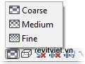
-2- Detail Level
-3- Model Graphics Style
-4- Shadows On/Off
-5- Show/Hide Rendering Dialog
-6- Crop/Do Not Crop View
-7- Show/Hide Crop Region
-8- Temporary Hide/Isolate
-9- Reveal Hidden Elements
View Scale
The view scale controls the plotting display of a view. It determines how the view will fit on a sheet. You select a scale value to adjust the display characteristics, such as line weights, of an object a utomatically. You can select a predefined scale value or specify a custom scale value, as shown.

The following illustrations show views with different scale values.
 |  |
View with a scale value of 6" = 1'-0" (1:2) | View with a scale value of 1/8" = 1'-0" (1:100) |
Detail Level
Detail Level affects the display of the component geometry. You can choose a display setting for the view from three detail levels: Coarse, Medium, and Fine.
Coarse displays only the outlines of walls, floors, and roofs. Medium and Fine display the compound structures of components.
The following illustrations show the plan view of a column with different detail levels.
 |  |
Coarse detail level | Fine detail level |
Model Graphics Style
Model Graphics Style controls the appearance of objects. The display styles available for Model Graphics Style are Wireframe, Hidden Line, Shading, and Shading with Edges, as shown.

You use the Wireframe and Hidden Line styles to duplicate the appearance of a standard printed page. For illustration and design review, you use Shading and Shading with Edges styles.
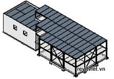
The following illustrations show a structural model with different model graphics styles.
 |  |
Wireframe style | Hidden Line style |
 |  |
Shading style | Shading with Edges style |
Shadows On/Off
You use Shadows On/Off to review design and drawings.
Zoning requirements sometimes restrict how the shadow of a building can fall on adjoining properties. You can check this by turning on the shadows using Shadows On.
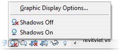
You can adjust the shadow properties and silhouette edge style using Graphic Display Options.
 |  |
Structural model with shadows turned on Structural model with shadows turned off
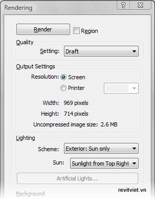
Show/Hide Rendering Dialog
You use Show/Hide Rendering Dialog to specify settings for the rendered image and start the rendering process. Show/Hide Rendering Dialog uses default options with which you can easily generate a quality rendered image without an in-depth understanding of the rendering technology. In the 3D Orthographic and 3D Perspective views, you can activate or hide this option on the View Control Bar. Selecting Show Rendering Dialog opens the Rendering dialog box, which contains settings and controls for creating rendered views that display the effects of sunlight, shadow, and materials.
The following illustration shows the Rendering dialog box.
Crop View
You can activate the crop view for view elements by selecting the Crop View instance parameter in the Instance Properties dialog box. When you select Crop View, it displays the elements only within the boundaries of the crop view. When you turn off the crop view by selecting Do Not Crop View, the elements within and outside the crop view boundaries are displayed.
 |  |
Callout view with crop boundary displayed but not activated | Callout view with crop boundary displayed and activated |
Show/Hide Crop Region
You use Show/Hide Crop Region to define the boundaries for a view. You can hide or show a crop region in a view, as required. When a crop region is visible, you can resize its edges by dragging the control grips.
 |  |
3D view with crop region activated and hidden | 3D view with crop region selected and control grips visible |
Temporary Hide/Isolate
You use Temporary Hide/Isolate to temporarily hide the selected objects or object categories in the active view, or isolate (display only) the selected object or category. This view parameter is useful when you want to view or edit only a few elements of a certain category.
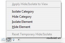
Temporary Hide/Isolate options
 | The objects hidden in a view using Temporary Hide/Isolate are not visible in the view window, but they are still a part of the view and are also printed. |
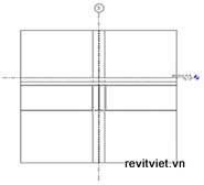
The following illustrations show the effect of the Temporary Hide/Isolate parameter on walls in a plan view when the Isolate Category option is selected.
 |  |
Upper wall selected | Wall category isolated |
Reveal Hidden Elements
You use Reveal Hidden Elements for quickly identifying elements hidden in the current view. You can identify them either by category, using visibility graphic overrides, or by element, using Hide in View from the shortcut menu of the selected element.
The following illustrations show a brace frame elevation view with hidden floor elements. In the illustration on the left, Reveal Hidden Elements is off and the floor elements are hidden in the view. In the illustration on the right, Reveal Hidden Elements is on and the elements currently hidden in the active view are displayed in magenta.
 |  |
Reveal Hidden Elements off | Reveal Hidden Elements on |
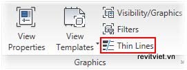
Thin Lines
You use the Thin Lines tool to toggle the display of line width in a model. Revit shows lines with applied width, by default, so that each view approximates how it prints according to drafting standards. With Thin Lines turned on, you can easily differentiate between closely spaced lines when you need to work in a cluttered part of a view. Thin Lines affects all the views. This tool is available on the Graphics panel of the View tab.
The following illustration shows the Thin Lines tool on the Graphics panel.
In the following illustration, when Thin Lines is turned on, you can view the exact intersection detail at the top of the wall, and when Thin Lines is turned off, the slanting roof hides the top of the wall.

-1- Thin lines turned off
-2- Thin lines turned on
-2- Thin lines turned on
Guidelines for Working with Views
The following recommended practices help you to work effectively with views.
- Familiarize yourself with duplicating and modifying views by using the Project Browser because the Project Browser and its associated shortcut menus are important tools for working with views. This helps you speed up your workflow and manage views easily, which is a basic skill in Revit.
- Familiarize yourself with the View Control Bar, which contains options that you will use while working with views. The View Control Bar helps you navigate and modify views quickly and easily. n Familiarize yourself with Temporary Hide/Isolate on the View Control Bar, which is useful for turning elements on and off as you work in a model.
- Study the Instance Properties and Visibility/Graphic Overrides dialog boxes for your working views because these two dialog boxes control what you see in any view. If you understand how to modify view properties, control visibility of elements, and change or override graphic display of elements in these two dialog boxes, you will be able to work more effectively.
- Adjust the crop region of the view after adding it, and then pin the view at the required position in the view window. This prevents you from inadvertently moving the view.
- Add drafting elements to the largest scale views because drafting elements are view-specific. Small scale views are generally used for placing objects, and larger scale views become important when you work on detailing and documentation. Placing the drafted items in large scale views is more efficient and saves time.
- Use dependent views for multistory projects with large floor plans. After you create the dependentviews for one level, you can quickly replicate them to other levels by right-clicking the parent view in the Project Browser and selecting Apply Dependent Views from the shortcut menu.
- Add drafting elements directly to views and not to sheets. When you move the views on a sheet, the elements placed in the view move with the view.
- Orbit about a particular element in a 3D view by selecting the element first and then rotating the view. This helps maintain the orientation of the view as you orbit.
- Open a view by double-clicking its name in the Project Browser. This is the quickest way to open a view.
- Select Close Hidden Windows on the Windows panel of the View tab to close all open views, except the active view in each project. This keeps your Switch Windows list manageable and conserves system resources.
- Dock, undock, and close the Project Browser to enlarge the view window when required. This provides a larger workspace.
- Select multiple views from the Project Browser using CTRL+select if you want to change the properties of multiple views simultaneously. This saves time and reduces the chance of errors.
- Open a 3D view and tile it when working in 2D plan, section, or elevation views. This helps in visualizing the effect of modifications made in the 2D view on the rest of the model.
Continue reading: Exercise: Explore and Create Views
No comments:
Post a Comment